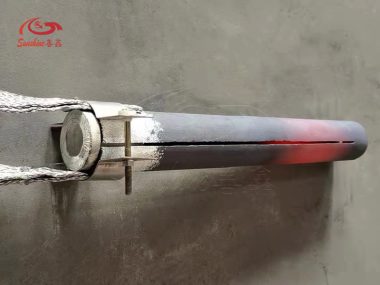
What are Silicon Carbide Heating Elements?
Silicon carbide heating elements, also known as sic heating elements or silicon carbide rods, are rod-shaped non-metal high-temperature heating elements made of high-quality green silicon carbide as the main raw material, processed, returned, high-temperature silicified and recrystallized.
Silicon carbide heating element is a time trusted heating element. It has the advantages of small hot-end resistance, long service life, and energy saving.Silicon Carbide heating elements are available in eight different basic configurations that extend heater life especially in corrosive environments.
Commonly used types are:
- sg silicon carbide heating element
- ed silicon carbide heating elements
- w silicon carbide heating elements
- sgr silicon carbide heating elements
- u silicon carbide heating elements
- ld silicon carbide heating elements
Physical Properties
Physical Properties of Silicon Carbide Heating Elements
| specific gravity |
2.6~2.8g/cm3 |
Bend strength |
>300kg |
| Hardness |
>9MOH’S |
Tensile strength |
>150Kg.cm3 |
| Porosity rate |
<30% |
Radiancy |
0.85 |
| Thermal Conductivity |
14-19W/m·℃
(1000℃) |
Specific Heat |
1.0kj/kg·℃
(25~1300℃) |
| Rupture Strength |
50Mpa(25℃) |
Coefficient Of Thermal Expansion |
1.0kj/kg·℃
(25~1300℃) |
Electrical characteristics
Sic heating elements has rather large specific resistance. When it is heated in air and the surface temperature of the hot zone reaches 1050℃, its resistance rate is 600-1400 mm2/m. Its resistance value changes as the temperature rises.
From room-temperature to 800℃ is negative value, over 800℃ is positive value nature curve.
All silicon carbide elements gradually increase in resistance during their life in operation and the rate at which this occurs is affected by the following factors:
- Element type
- Element Specific Loading (W/cm2)
- Operating Temperature
- Process Atmosphere
- Mode of operation - continuous or intermittent
- Operating practices
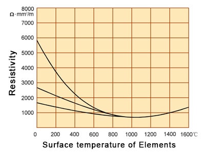
Silicon carbide heating elements electrical characteristics
Element Surface Loading
The key factor to the optimum service life of the element is to select the surface load of the element correctly according to the furnace construction, atmosphere and temperature below.
The curves show maximum specific element loading for different element types operated in air. These values may be used as a guide, but for maximum element life a lower loading should be used wherever possible.
A lower loading may also be required where elements are to be operated in reducing or other process atmospheres, to maintain element temperatures within the limits, see table below.
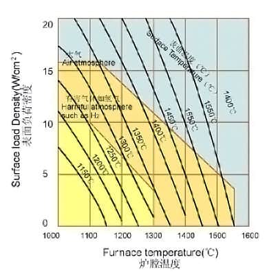
Silicon carbide heating elements element surface lodading
| Temperature(℃) |
Linear expansion coefficient
(10-6m/℃) |
Heat conductivity
(Kcal/M hr ℃) |
specific heat
(cal.g℃) |
| 0 |
/ |
/ |
0.148 |
| 300 |
3.8 |
/ |
/ |
| 400 |
/ |
/ |
0.255 |
| 600 |
4.3 |
14-18 |
/ |
| 800 |
/ |
/ |
0.294 |
| 900 |
4.5 |
/ |
/ |
| 1100 |
/ |
12-16 |
/ |
| 1200 |
4.8 |
/ |
0.325 |
| 1300 |
/ |
10-14 |
/ |
| 1500 |
5.2 |
/ |
/ |
常用的silicon carbide heating elements类型有:
<
Therefore, silicon carbide rods are widely used in various high-temperature electric furnaces and other electric heating equipment in the industries of magnetic materials, powder metallurgy, ceramics, glass, metallurgy and machinery.
 Silicon carbide rods in the furnace
Sic heating elements VS metal electric heating elements
Compared with metal electric heating elements, Sic heating elements have the characteristics of high operating temperature, oxidation resistance, corrosion resistance, long life, low deformation, and convenient installation and maintenance.
FAQ:
How to choose power supply equipment?
Power supply equipment should be selected with a large regulating range voltage and it is a stable and continuous voltage regulating equipment, such as magnetic voltage regulator, silicon controlled DC voltage regulator, etc. If you choose a stage voltage regulator transformer, you should also choose a transformer with a small voltage difference .
What are the connection of silicon carbide rods?
The connection mode of silicon carbon rod element can be series or parallel, and parallel is the best. When used in series, the number of branches in series should not be more than 3.
The Common connection methods and their calculation formulas are listed in the following datatable.
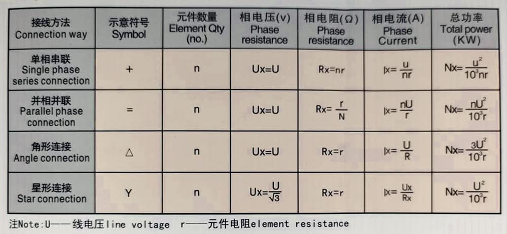
Power calculation of several common wiring methods
Installation and Operation of Element
Horizontal and vertical orientation are the more common installation method. Special attention must be paid when mounting to ensure that the elements are not placed in tension. There should be adequate space to allow for the furnace and elements to expand and contract independently.
When mounting elements vertically, they must be supported on the lower end by electrically insulated supports, or from above using support pins on an isolating plate of sufficient strength to support the weight of the elements.The elements ends should extend beyond the furnace cold face by a minimum distance of 76.2mm to 101.6mm.
- 1) In order to keep furnace temperature and the load-bearing uniform of each element, before installation, resistance distribution must be carried out. The resistance value deviation of each group should be below 10%.
- 2) As the element is very brittle, be careful while install and maintain to avoid any damage.
- 3) When start to operate the furnace, raise voltage slowly and gradually, never give full load at one time, or the heating element will be damaged by over current impulse.
- 4) To use the elements, you should prepare the adjustable transformer or silicon controlled transformer, voltage meter, current meter and auto control temperature meter etc. During the working, the voltage should be increased to maintain the furnace normal temperature because the resistance value will go up gradually caused y the oxidation of element. When the voltage gets to the up limit of the requirement, the furnace should be stoopoped, change the way of wire connection and then continue work.
- 5) In the course of long operation of the furnace, if any individual heating element is damaged owing to certain reasons and should be changed, you should replace it with proper one whose resistance value corresponds to that of the old one, never use a new heating element random. If the heading element is much damaged or its resistance value increases too much and cannot reach the furnace temperature, it is better to replace the heating elements with mew ones. Test and mark the resistance value of the old elements having been replaced (with voltmeter and ammeter) and distribute them in low temperature area.
- 6) Before the new furnace of the furnace that has not been used for a long time is used, they must be dryinged. When drying them, it is better to use old elements or other heat source.
- 7) When firing appatatus or material, if there is water ejection, the furnace should have holes to eject water vapor or other waste gases in order to protect the elements service life.
How to prolong the element’s service life?
The resistance value of the heating element will increase and age with the extension of service time. When the resistance of the element increases to 3 times the initial resistance value, it is regarded as the end of service life. There are several factors affecting the aging and life reduction of heating elements:
- Operating temperature
- Electrical loading (usually expressed in watts per square inch or watts per square centimeter of elements radiating surface)
- Atmosphere
- Type of operation (continuous or intermittent)
- Operating and maintenance techniques
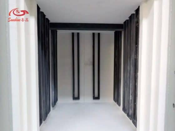
High temperature laboratory furnace cross sectional view
When used in 1450 ℃ clean oxidation atmosphere, the heating element can obtain a relatively long service life. In order to achieve the best service life, the surface load as low as possible should be considered when designing the furnace, and 3-8w/cm² is recommended
